Port Configuration

|
Note |
|
The computer from which the router is being configured should be connected to Ethernet port 1 throughout
the configuration process. Otherwise, one will be repeatedly locked out of the router during the configuration
process.
|
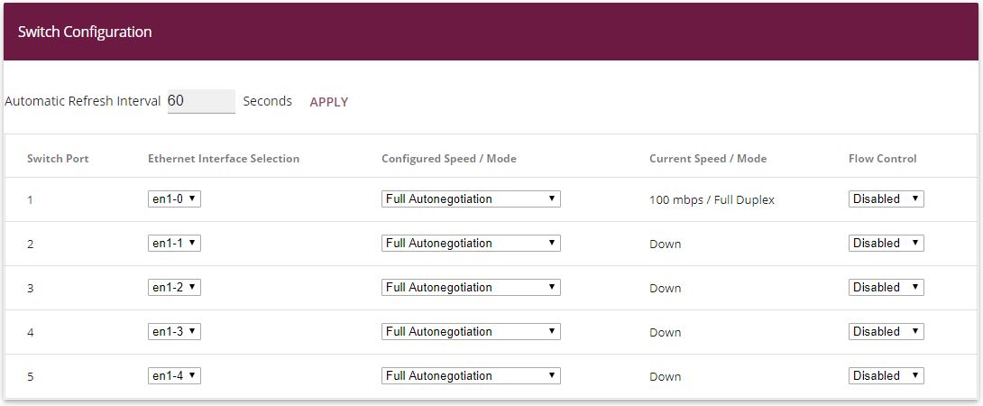
First of all, the Ethernet ports are configured as separate interfaces, and a separate interface is
assigned to each port, in ascending order, beginning with en1-0.
-
Go to
Physical Interfaces -> Ethernet Ports -> Port Configuration.
Proceed as follows to assign the ports to the interfaces:
-
Under
Ethernet Interface Selection select
en1-0
to
en1-4
for the
Switch Ports
1 and
5 from the dropdown menu.
-
Confirm with
OK.
The WAN and Internet access is then set up. The
GUI™ has a
wizard to configure the Internet access. To do this, go to the following
menu:
-
Go to
Assistants -> Internet Access-> Internet Connections -> New.
-
For
Connection Type, select the appropriate connection type for your
Internet access, in our example
External gateway/cable modem
.
-
Click on
Next to configure a new Internet connection.
We shall now describe the setup for an external gateway:
-
Under
Physical Ethernet Port select the physical Ethernet port to
which the xDSL modem or the Internet uplink is connected, in this case
ETH5
.
-
For
Internet Service Provider, select
--User-defined---
.
-
Deselect the
IP parameters obtained dynamically option.
-
Under
Local IP Address, enter your Internet access data, e. g.
1.2.3.4
.
-
For
Gateway IP Address enter the gateway's IP address, e. g.
1.2.3.1
.
-
Enter the relevant
Netmask, e. g.
255.255.255.0
.
-
For
DNS Server 1 enter the name server's IP address, e. g.
1.2.3.1
.
-
Press
OK to confirm your entries.
Variant:
-
If the uplink is a provider's xDSL access, you can, instead, select
Internal modem
as the
Connection Type in the first step of the Internet access wizard.
-
In this case, the internal
Network Interface, instead of being called
en1-4
, is usually called
WAN_Providername
and, when the configuration has been completed in
the menu
Network -> Routes -> IP Routes, appears as the interface for the
default gateway (in the simplest case, this is the only entry with the target IP address and netmask the same
0.0.0.0
).
-
The
interface name is relevant for subsequent configuration steps
when setting up the firewall.
|
|
Note |
|
This interface is not to be confused with the (underlying)
ethoa
interface which is also present.
|
The LAN interfaces are then configured.
You configure the Ethernet interface by editing the default entry. To do this, click the
 icon next to the existing
<en1-0> entry.
icon next to the existing
<en1-0> entry.
-
Go to
LAN -> IP Configuration -> Interfaces ->
.
Proceed as follows to configure the Ethernet interface:
-
Enter the static
IP Address
10.0.0.1
and the
Netmask
255.255.255.0
.
-
Confirm with
OK.
|
|
Note |
|
After you have confirmed the configuration with
OK, you have locked yourself (just the once) out of the router.
Log back onto the newly set up
IP Address
10.0.0.1
for
en1-0
(your own computer's network configuration may have to be
changed before doing this).
|
-
The static
IP Address
10.0.1.1
with
Netmask
255.255.255.0
is then set up on the Ethernet interface
en1-1
.
-
Confirm with
OK.
-
Finally, the Ethernet interface
en1-2
is set up with the static
IP Address
10.0.2.1
and with the
Netmask
255.255.255.0
. The Ethernet interface
en1-3
remains unused.
-
Confirm with
OK.
In the next step, two virtual interfaces based on
en1-0
are added.
-
Go to
LAN -> IP Configuration -> Interfaces -> New.
Proceed as follows to configure the first virtual interface:
-
For
Based on Ethernet Interface, select the interface
en1-0
.
-
Assign
VLAN ID
10
to the interface.
-
For
IP Address / Netmask, click
Add.
-
The first virtual interface is given the static
IP Address
10.0.10.1
and the
Netmask
255.255.255.0
.
-
Confirm with
OK.
You configure the second virtual interface as follows:
-
For
Based on Ethernet Interface, select the interface
en1-0
.
-
Assign
VLAN ID
20
to the interface.
-
For
IP Address / Netmask, click
Add.
-
The second virtual interface is given the static
IP Address
10.0.20.1
and the
Netmask
255.255.255.0
.
-
Confirm with
OK.
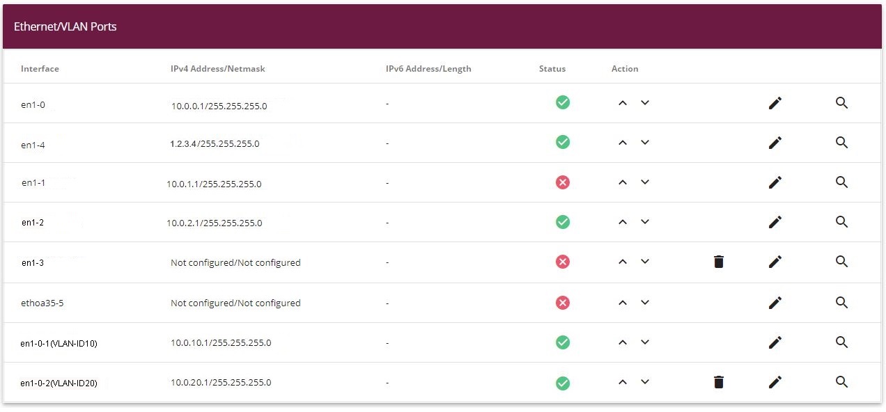
Results:
System access and firewall setup
Administrative access to the device is configured in the
Access menu. Firstly, all of the router's configuration services are
restricted to the administrative Ethernet interface
en1-0
.
-
Go to
System Management -> Administrative Access -> Access .
Proceed as follows:
-
For the
Interface
en1-0
, select the router's configuration services
Telnet
,
SSH
,
HTTP
,
HTTPS
,
Ping
and
SNMP
.
-
On all the other interfaces, only
Ping
should be allowed. We do not recommend that you also block
Ping, because this makes it unnecessarily difficult to search for errors in the LAN (with no additional
security).
-
Click
OK.
Setting the
Passwords is another basic system setting. Make sure you change the
passwords to prevent unauthorised access to the device
-
Go to
System Administration -> Global Settings -> Passwords.
-
Enter the password for the user name
admin
.
-
Confirm the password by entering it again.
-
Click
OK.
The
Firewall for the LAN is then set up. Define a group that contains all the
services that the router itself is to offer in the LAN.
-
Go to
Firewall -> Services -> Groups -> New.
Proceed as follows:
-
For
Description, enter
Local-Services
for the group.
-
Select the
Members of the group, e. g.
echo
,
dns
,
dhcp
,
ntp
. To do this, activate the field in the
Members column.
-
Confirm with
OK.
In the next step, you define the firewall's address lists. By default,
ANY
is the only entry.
-
Go to
Firewall -> Addresses -> Address List -> New.
Proceed as follows:
-
Under
Description, enter
Broadcast
.
-
For the
Address / Subnet, enter
255.255.255.255
and
255.255.255.255
.
-
Confirm with
OK.
Define other LAN IP address lists.
-
For
Employee LAN GW
(en1-1) the
IP Address
10.0.1.1
with the
Netmask
255.255.255.255
.
-
Confirm with
OK.
-
For
Guest LAN GW
(en1-2) the
IP Address
10.0.2.1
with the
Netmask
255.255.255.255
.
-
Confirm with
OK.
-
For
Employee WLAN GW
(en1-0-1) the
IP Address
10.0.10.1
with the
Netmask
255.255.255.255
.
-
Confirm with
OK.
-
For
Guest WLAN GW
(en1-0-2) the
IP Address
10.0.20.1
with the
Netmask
255.255.255.255
.
-
Confirm with
OK.
|
|
Note |
|
The IP addresses in the firewall need to match the interfaces concerned for IP configuration (and be
modified if the configuration is changed). The mask must always be 255.255.255.255 and has nothing to do with the
netmask of the networks concerned. The mask restricts the range of the relevant address list to precisely the one IP
address that was entered.
|
The list of configured addresses now looks like this:
Now you still need to define the interfaces for the individual user groups.
-
Go to
Firewall -> Interfaces-> IPv4 Groups -> New.
Proceed as follows to set up the
Employees
group:
-
Enter
Staff
as the
Description for the group.
-
From the interfaces that have been configured, select
LAN_EN1-1
and
LEASED_EN1-0-1
as
Members of the group.
-
Confirm with
OK.
Define another group
Guest
as follows:
-
Enter
Guest
as the
Description for the group.
-
Select
LAN_EN1-2
and
LEASED_EN1-0-2
as
Members of the group.
-
Confirm with
OK.
Set up the interfaces group
Users
(staff and guests).
-
Enter
User
as the
Description for the group.
-
As
Members of the group, select
LAN_EN1-1
,
LAN_EN1-2
,
LEASED_EN1-0-1
and
LEASED_EN1-0-2
.
-
Confirm with
OK.
The list of configured groups now looks like this:
Now the actual firewall rules can be created based on these definitions. Firstly, the rule for the
administrators area in
en1-0
must be defined (otherwise one will be locked out totally and
immediately).
-
Go to
Firewall -> Policies -> IPv4 Filter Rules ->New.
Proceed as follows:
-
Select the packet's
Source, in this case
LAN_EN1-0
.
-
Set the
Destination to
ANY
. Neither the destination interface or the destination address
will be checked.
-
For
Services, select
any
(all the services).
-
Select the
Action that is to be applied, in this case
Access
. The packets are forwarded on the basis of the
entries.
-
Confirm with
OK.
-
As the next rule, the
Source group
Staff
is to be granted access to the
Destination group
Users
via
Services
any
.
-
Confirm with
OK.
-
After that, a rule is created which is used to permit access from the
Source group
Guest
to the
Destination group
Guest
via
Services
any
.
-
Confirm with
OK.
-
Another rule should give all the
Users
access to the Internet: As the
Source, select
Users
, as the
Destination, select
LAN_EN1-4
, and as the
Service, select
any
.
-
Confirm with
OK.
|
|
Note |
|
If an Internet access via an internal xDSL modem has been set up, instead of
LAN_EN1-4
, you need to select the relevant WAN interface (
WAN_Providername
) as the
Destination.
|
Up to this point, the only access rules to have been defined are those for network areas connected via the
router, and nobody outside the system area at the interface
en1-0
is permitted to access IP addresses defined locally in the
router.
To be able to use the basic services such as
dns
,
dhcp
etc., you need to explicitly allow
access to the IP address of the interface concerned which is linked
to the router.
-
Go to
Firewall -> Policies -> IPv4 Filter Rules -> New.
Proceed as follows:
-
As the
Source of the packet, select the
Users
group.
-
As the
Destination, select the
Broadcast
address that was defined previously.
-
For
Service, select the service group that the users are to be
permitted to access, in this case
Local-Services
.
-
Select the
Action that is to be applied, in this case
Access
. The packets are forwarded on the basis of the
entries.
-
Confirm with
OK.
-
In the next rule you select the
Source
LAN_EN1-1
. As the
Destination, select the
Staff LAN GW
that was defined previously, as the
Service select
Local Services
and, for the
Action, select
Access
.
-
Confirm with
OK.
-
In the next rule you select the
Source
LAN_EN1-2
. As the
Destination, select the
Guests LAN GW
address that was defined previously, as the
Service select
Local-Services
and, for the
Action, select
Access
.
-
Confirm with
OK.
-
In the next rule, as the
Source you select
LEASED_EN1-0-1
, as the
Destination you select the
Staff WLAN GW
address which was defined previously, as the
Service you select
Local services
and as the
Action you select
Access
.
-
Confirm with
OK.
-
In the final rule, as the
Source you select
LEASED_EN1-0-2
. As the
Destination, select the
Guests WLAN GW
address that was defined previously, as the
Service select
Local Services
and, for the
Action, select
Access
.
-
Confirm with
OK.
The list of configured filter rules now looks like this:
The firewall automatically rejects any other data which does not fit with the above rules. So there is no
need to create any explicit exclusion rules to reject the other data traffic. This also means that, with the current
firewall configuration, any IP data traffic on the router and to the LAN that is initiated by the WAN/Internet (
en1-4
in our example) is suppressed. If access from outside is required,
separate firewall rules need to be defined for this purpose with the WAN interface (in this case
LAN_EN1-4
) as the source.
To finish, check whether the firewall is enabled. To do this, go to the following menu:
-
Go to
Firewall -> Policies -> Options .
The
IPv4 Firewall Status option must be set to
Activated
.
DHCP server configuration
After that, 5 DHCP servers, in all, now need to be configured to match the relevant interface's
network.
-
Go to
Local Services -> DHCP Server -> IP Pool Configuration -> New.
Proceed as follows to set up the IP address pool for the slave APs:
-
Enter a unique
IP Pool Name, e. g.
Slave APs
.
-
Enter an
IP Address Range. In our example, we shall take the IP address
range from
10.0.0.10
to
10.0.0.29
. The size of the IP address range depends on the maximum
number of access points required (6 plus reserve in our example). So the remaining addresses can be used for other
infrastructure in the same network.
-
Press
OK to confirm your entries
In the
Local Services -> DHCP Server -> DHCP Configuration -> New menu, you can perform additional
configuration.
Proceed as follows:
-
Under
Interface, select the logical interface
en1-0
.
-
Select a valid
IP-Pool, here e. g.
Slave-APs
.
-
Click
Advanced Settings.
-
Under
Gateway leave the setting
Use Router as Gateway
. The current IP address of the interface
en1-0
is propagated as the default gateway to the DHCP
devices.
-
For
DHCP Options, click
Add.
-
Select the option
DNS Server
and enter the IP address of the interface
en1-0
, in this case
10.0.0.1
.
-
Click
Add again.
-
Select the option
CAPWAP Controller
and enter the IP address of the interface
en1-0
, in this case
10.0.0.1
.
-
Press
OK to confirm your entries.
No other DHCP options are required for the slave access points to operate correctly.
In the next step, you define the
DHCP Pool
Staff WLAN
.
Go to Local Services -> DHCP Server -> IP Pool Configuration -> New.
-
For
IP Pool Name, enter e. g.
Staff-WLAN
.
-
Enter an
IP Address Range. In our example, the IP address range from
10.0.20.10
to
10.0.20.254
.
-
Press
OK to confirm your entries.
-
Go to
Local Services -> DHCP Server -> DHCP Configuration -> New.
-
Under
Interface, select the interface
en1-0-1
.
-
For
IP Pool Name, enter e. g.
Staff-WLAN
.
-
Click
Advanced Settings.
-
Under
Gateway leave the setting
Use Router as Gateway
.
-
For
DHCP Options, click
Add.
-
Select the option
DNS Server
and enter the IP address of the interface
en1-0
, in this case
10.0.10.1
.
-
Press
OK to confirm your entries.
Proceed as follows to set up another IP address pool for the
Guest WLAN
:
Go to Local Services -> DHCP Server -> IP Pool Configuration -> New.
-
For
IP Pool Name, enter e. g.
Guest-WLAN
.
-
Enter an
IP address range. In our example, the IP address range from
10.0.20.10
to
10.0.20.254
.
-
Press
OK to confirm your entries.
-
Go to
Local Services -> DHCP Server -> DHCP Configuration -> New.
-
Under
Interface, select the interface
en1-0-2
.
-
Select a valid
IP-Pool, here e. g.
Guest-WLAN
.
-
Click
Advanced Settings.
-
Under
Gateway leave the setting
Use Router as Gateway
.
-
For
DHCP Options, click
Add.
-
Select the option
DNS Server
and enter the IP address of the interface, in this case
10.0.20.1
.
-
Press
OK to confirm your entries.
Do the same thing to configure the
DHCP Pool for
Staff Ethernet
.
Go to Local Services -> DHCP Server -> IP Pool Configuration -> New.
-
For
IP Pool Name, enter e. g.
Staff-Ethernet
.
-
Enter an
IP Address Range. In our example, the IP address range from
10.0.1.10
to
10.0.1.254
.
-
Press
OK to confirm your entries.
-
Go to
Local Services -> DHCP Server -> DHCP Configuration -> New.
-
Under
Interface, select the interface
en1-1
.
-
Select a valid
IP-Pool, here e. g.
Staff-Ethernet
.
-
Click
Advanced Settings.
-
Under
Gateway leave the setting
Use Router as Gateway
.
-
For
DHCP Options, click
Add.
-
Select the option
DNS Server
and enter the IP address of the interface, in this case
10.0.1.1
.
-
Press
OK to confirm your entries.
Then configure the
DHCP Pool for
Guest Ethernet
.
Go to Local Services -> DHCP Server -> IP Pool Configuration -> New.
-
For
IP Pool Name, enter e. g.
Guest-Ethernet
.
-
Enter an
IP address range. In our example, the IP address range from
10.0.2.10
to
10.0.2.254
.
-
Press
OK to confirm your entries.
-
Goto
Local Services -> DHCP Server -> DHCP Configuration -> New.
-
Under
Interface, select the interface
en1-2
.
-
Select a valid
IP-Pool, here e. g.
Guest-Ethernet
.
-
Click
Advanced Settings.
-
Under
Gateway leave the setting
Use Router as Gateway
.
-
For
DHCP Options, click
Add.
-
Select the option
DNS Server
and enter the IP address of the interface, in this case
10.0.2.1
.
-
Press
OK to confirm your entries.
The list of configured DHCP pools now looks like this:
WLAN Controller setup
Now the
Wireless LAN Controller on interface
en1-0
can be enabled.
-
Go to
Wireless LAN Controller -> Controller Configuration -> General.
Proceed as follows:
-
The
Region must be set up to match the location of the access
points,
Germany
in our example. This means that the access points' WLAN
wireless modules will only run inside the legally permitted framework of the country concerned.
-
As the WLAN controller's
Interface, select
en1-0
.
-
When the interface has been selected, the
DHCP Server settings automatically change to
Internal
.
-
IP Address Range displays the address range that was
configured in the DHCP Pools menu on interface
en1-0
, in this case
10.0.0.10
-
10.0.0.29
.
-
Leave the
Slave AP location set to
Local (LAN)
.
-
Confirm with
OK.
The settings are now enabled and the WLAN controller is started.
The
Wireless Networks (VSS) are now edited.
Go to the following menu to set up your WLAN network:
-
Go to
Wireless LAN Controller -> Slave AP Configuration->Wireless Networks
(VSS).
Configure the WLAN connection by editing the default entry. To do this, for the existing entry
<vss-1> click the
symbol.
Proceed as follows:
-
Under
Network Name (SSID) enter e. g.
Staff
. The
Visible option remains enabled.
-
Set the
Security Mode to
WPA-PSK
.
-
Leave the
WPA Mode set to
WPA and WPA 2
.
-
The
WPA Cipher is set to
TKIP
.
-
Set the
WPA2 Cipher to
AES
.
-
The
Preshared Key is the WLAN access password for all the
employees. Enter an ASCII string with 8 - 63 characters.
-
Enable the
VLAN option.
-
Enter the
VLAN-ID
10
.
The result of this is that all the data that from the WLAN devices connected later to the SSID
Employees
is marked by the slave access points in the Ethernet with
the
VLAN-ID
10
. This means that the employee data traffic between router and
access points is a standalone network area at the Ethernet level (layer 2), too.
-
Confirm with
OK.
Select the
New button to configure a wireless network for the guest access.
-
Go to
Wireless LAN Controller -> Slave AP Configuration->Wireless Networks
(VSS)-> New.
Proceed as follows:
-
Under
Network Name (SSID) enter
Guest
for example. The
Visible option remains enabled.
-
Set the
Security Mode to
WPA-PSK
.
-
Leave the
WPA Mode set to
WPA and WPA 2
.
-
The
WPA Cipher is set to
TKIP
.
-
Set the
WPA2 Cipher to
AES
.
-
The
Preshared Key is the WLAN access password for all the guests.
Enter an ASCII string with 8 - 63 characters.
-
Enable the
VLAN option.
-
Enter the
VLAN-ID
20
.
-
Confirm with
OK.
In the next step, the
Radio Profiles are edited. You configure the
Radio Profiles by editing the default entry.
-
Go to
Wireless LAN Controller -> Slave AP Configuration-> Radio Profiles
.
-
Where you have the existing entry
<2.4 GHz Radio Profile> , click the
symbol.
Proceed as follows:
-
The wireless module profile's
frequency range is left at
2.4 GHz In/Outdoor
.
-
For
Wireless Mode, select
802.11 g/n
. The result of changing the
Wireless Mode is that old WLAN devices which have become
relatively rare and which only talk 802.11b will no longer be able to use the WLAN. The great advantage of only
allowing 802.11g/n is that the data throughput for all the connected WLAN devices is no longer automatically and
drastically reduced as soon as a WLAN device attempts to get into the WLAN network in 802.11b mode.
-
Enable the option
Burst Mode to increase the transmission speed.
-
Click
Advanced Settings.
-
Select the
Channel Plan you require.
User-defined
enables you to select the channels you require
yourself.
-
Under
User Defined Channel Plan, select the permitted channels,
1
,
5
,
9
and
13
. This channel plan is the recommended ideal channel plan for
every country where channels 1 to 13 are allowed and it does not have any (significant) frequency overlaps with
802.11g/n. This means that the access points have more choices for using a channel with minimal interference, which
improves the performance and reliability of the entire WLAN.
-
Enable the
Short Guard Interval function in order to reduce the guard
interval (= time between transmitting two data symbols) from 800 ns to 400 ns.
-
Leave the remaining settings unchanged and confirm them with
OK.
All the necessary profiles have now been set up in the WLAN controller.
Now the access points are enabled and set up. The
Slave Access Points menu displays a list of all the APs found using the
Wizard (here e.g. a
bintec W2003ac™).
-
Go to
Wireless LAN Controller -> Slave AP Configuration-> Slave Access
Points.
|
|
Note |
|
If no access points are displayed, we recommend that you re-check the DHCP server settings for the
DHCP pool
slave APs
, whether it is connected to the correct interface (
en1-0
in this case) and whether the CAPWAP option has been set
correctly (
10.0.0.1
in this case). Also check whether another DHCP server is
enabled on a different device in the system area. Switch all the access points off and back on so that they get the
network configuration settings from the DHCP server again.
|
Finally, the
Radio Profiles that were configured previously and the
wireless networks are set up for each access point.
-
Go to
Wireless LAN Controller -> Slave AP Configuration-> Slave Access Points
.
Proceed as follows:
-
For
Location enter e. g.
Meeting Room
.
-
For
Description enter e. g.
Marketing
.
-
Leave the
CAPWAP Encryption set to
Enabled
.
-
Leave the
Operation Mode set to
On
. This results in all the settings being used in the selected
radio profiles.
-
As the
Active Radio Profile, select the wireless module profile that
was configured previously, in this case
2.4 GHz Radio Profile
.
-
Leave the
Channel set to
Auto
(this means it is determined dynamically using the wireless
profile's channel plan and the WLAN environment).
-
For
Assigned Wireless Networks (VSS), the two configured wireless
networks
Staff
and
Guest
are assigned to the wireless module.
-
Confirm with
OK.
Configure all the access points that have been found in the same way.
|
|
Note |
|
Every access point must be given a unique location name. Otherwise there will be no way of distinguishing
between the access points once they are running.
|
The list of configured access points (here e. g. a
bintec W2003ac™) now looks like this:
Once all the access points have been set up, there is a short initialization phase and they are given the
status
Managed
, so they are now up and running. The WLAN controller is also
blocking them against any sort of external configuration access.
Choose whether the selected Access Pont is to be managed by the WLAN Controller by clicking the
 button or the
 button in the
Action column.
button in the
Action column.
You can disconnect the Access Point from the WLAN Controller and therefore remove it from your WLAN
infrastructure by click on the
button. The Access Point then
receives the
Discovered
status, but is no
longer
Managed
.
The WLAN channels currently being used which are displayed on the overview page are not yet optimal because
during the initial startup, the access points were only able to tune in to the general WLAN environment.
Under
New Channel Setting, click the
START button to be able to optimally tune the assigned channels to one
another.
When the channel setting is complete, adjacent access points ought to have different channels.
This concludes the configuring of the WLAN controller and of the router as an access gateway. Save the
configuration with
Save configuration and confirm the selection with
OK.
|
|
Note |
|
In some cases it may occur that individual adjacent access points still have the same channel even after
the channels have been newly set. This always occurs if adjacent access points cannot identify one another
sufficiently, or at all, with the WLAN. If the access points are correctly spaced out, one frequent reason for this is
strong local interference from third party access points, or a difficult building structure such as fire doors made of
steel (usually closed) between two adjacent building areas. In such cases we recommend that, for each access point in
the pairs affected, you manually set a fixed channel (which fits with the channel plan) for the wireless modules and
you re-run the search for new channels. The result of this is that the other access points which were configured using
the automatic channel selection are assigned channels which suit the environment of the access points that have been
fixed manually.
|
| Copyright© Version 01/2020 bintec elmeg GmbH |
|