Configuring the IPTV Multicast data access |
To configure the virtual LAN interfaces for the Multicast access, go to the following menu:
Go to LAN -> IP Configuration -> Interfaces -> New.

LAN->IP Configuration ->Interfaces-> New
Proceed as follows:
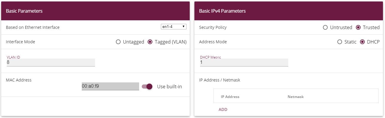
Under Based on Ethernet Interface, select the logical Ethernet interface that has been assigned to the physical Ethernet port used above. For Ethernet port ETH5, this is the en1-4 interface (on this, see the explanation below).
Set the Interface Mode to Tagged (VLAN) . You use this option to assign the interface to a VLAN.
In the VLAN-ID input field, enter the VLAN ID 8 which is to be used.
Set the Address Mode to DHCP . An IP address is assigned to the interface dynamically via DHCP.
Click Advanced Settings.
Disable the DHCP Broadcast Flag option.
Leave the remaining settings unchanged and confirm your entries with OK.
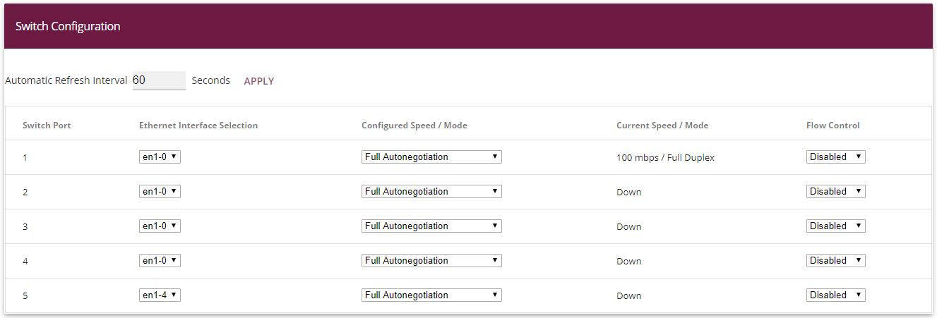
The assignment between the physical Ethernet port and the logical Ethernet interface can be flexibly configured in the routers with an integrated switch. Ex works, the following assignment usually applies:
| Physical Ethernet Port | Logical Ethermet Interface |
|---|---|
| ETH1 to ETH4 | en1-0 |
| ETH5 | en1-4 |
For detailed information on the assigned that has been configured in your case, go to the Physical Interfaces menu. For the bintec be.IP™ router that is used in the workshop, it looks like this ex works:
Go to Physical Interfaces ->Ethernet Ports->Port Configuration.
Physical Interfaces->Ethernet Ports->Port Configuration
Now you will configure the IGMP proxy required to receive the IPTV Multicast data.
Go to Multicast -> IGMP-> IGMP-> New .


Multicast -> IGMP-> IGMP-> New
Proceed as follows to configure the IGMP proxy.
Under Interface, select the logical Ethernet interface which the Media Box or client PCs are connected to. In our example, they are Ethernet ports ETH1 to ETH4. Based on the above assignment, the logical Ethernet interface LAN_EN1-0 needs to be selected.
Select Routing for Mode.
Click Advanced Settings.
Enable the IGMP Proxy option.
As the Proxy Interface, select the generated VLAN interface LAN_EN1-4-1 .
Leave the remaining settings unchanged and confirm your entries with OK.
The completed configuration looks as follows (the entry for the IGMP proxy interface ( en1-4-1 ) is generated automatically):

Multicast-> IGMP-> IGMP
The routing of IP Multicast packets to the bintec router is disabled by default. In the following configuration step, you enable the Multicast routing function on the router. To do this, go to the following menu:
Go to Multicast -> IGMP->Options.

Multicast -> IGMP->Options
Proceed as follows:
Set the IGMP status to Up or Auto .
Confirm your entry with OK.

|
Note |
|---|---|
|
A one-off confirmation of the configuration page through OK is essential. This also applies if the IGMP Status has already been set to Auto or Active . |
|
For security reasons, and to ensure that video on-demand services work, the NAT function needs to be disabled.
Go to Networking -> NAT -> NAT Interfaces.

Networking -> NAT -> NAT Interfaces
Under NAT active, enable the LAN_EN1-4-1 interface.
Confirm with OK.
| Copyright© Version 08/2020 bintec elmeg GmbH |