
Assistants -> Internet -> Internet Connections -> New -> Next
Configure the gateway at head office |
Two ADSL Internet connections are used in parallel at the head office location, to improve reliability and achieve greater bandwidth. These Internet accesses are configured using the Wizard.
Go to Assistants -> Internet -> Internet Connections -> New.
For Connection Type, select Internal ADSL Modem .
Click on Next to configure a new Internet connection.
Enter the required data for the connection.
Assistants -> Internet -> Internet Connections -> New -> Next
Proceed as follows to configure an Internet access:
Under Description enter e. g. ADSL-1 .
For Type, select User-defined via PPP over Ethernet (PPPoE) .
For User Name, enter the name that your provider has given you, e. g. ADSL-Username .
Enter the Password that your provider has given you, e. g. test12345 .
In the Always active field, specify whether or not the Internet connection should always be on. Only activate this option if you have Internet access with a flatrate.
Press OK to confirm your entries.
To set up the second ADSL connection, run the wizard again.
Go to Assistants -> Internet-> Internet Connections -> New.
For Connection Type, select External xDSL Modem .
Click on Next to configure a new Internet connection.
Enter the required data for the connection.
Assistants -> Internet -> Internet Connections -> New -> Next

|
Note |
|---|---|
|
The message you get when you create the second ADSL connection may be ignored. The IP load distribution avoids routing conflicts due to multiple standard routes! |
|
Proceed as follows to configure the second Internet connection:
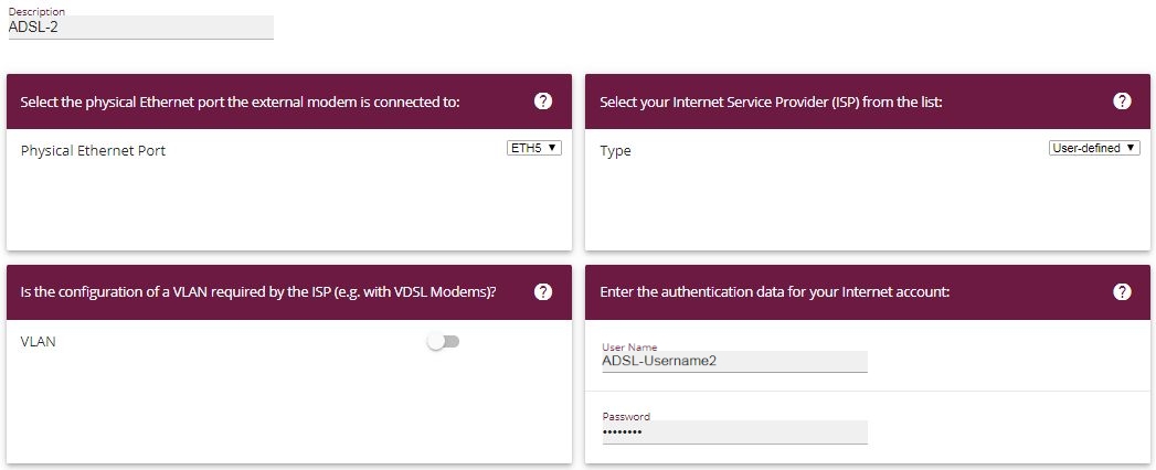
Under Description, enter a name for the Internet connection, e. g. ADSL-2 .
Under Physical Ethernet Port select the physical Ethernet port to which the xDSL modem is connected, in this case ETH5 .
For User Name, enter the access data that your provider has given you, e. g. ADSL-Username2 .
Enter the Password that your provider has given you, e. g. test12345 .
Press OK to confirm your entries.
When the configuration is complete, the wizard for configuring Internet connections will show two entries.
Go to Assistants -> Internet-> Internet Connections.

Assistants -> Internet -> Internet Connections
A load balancing group needs to have been created before you can set up the IP load distribution.
Go to Network -> Load Balancing -> Load Balancing Groups -> New.

Network ->Load Balancing->Load Balancing Groups->New
To create a load balancing group, proceed as follows:
Under Group Description, enter a name for the load balancing group, e. g. Internet access .
For Distribution Policy, select the method that will be used to distribute the data, here Session-Round-Robin (for load distribution based on IP sessions).
The two ADSL Internet accesses can then be added to this load balancing group.
To do this, click Add.

Network ->Load Balancing->Load Balancing Groups->Add
Proceed as follows:
For Interface, select the first ADSL access WAN_ADSL-1 .
Enter 50 % for Distribution Ratio.
Click Apply.
Add the second ADSL line with Add.
For Interface, select the second ADSL access WAN_ADSL-2 .
Enter 50 % for Distribution Ratio.
Click Apply.
Results:

Network -> Load Balancing -> Load Balancing Groups
After this configuration step, the two Internet connections can be used with the IP load distribution. In this scenario, activating the IP load distribution means that no advanced routing entries are required to enable the VPN IPSec tunnel to be created.
In this scenario, the VPN IPSec connections are always set up from the branch office gateway to the head office gateway. The same IPSec Phase 1 and Phase 2 profile can be used for both tunnel connections. For this purpose, create two new VPN tunnels.
Go to VPN -> IPSec -> IPSec Peers -> New.


VPN-> IPSec-> IPSec Peers-> New
To add a new connection, proceed as follows:
Set the Administrative Status to Up . The peer is available for setting up a tunnel immediately after saving the configuration.
For Description, enter a description of the peer which identifies it, e. g. Branch1_Peer-1 .
No address is entered for Peer Address, because the VPN tunnel is always set up from the branch office gateway to the head office gateway.
For Peer ID, the ID type E-mail Address and the ID value Branch1_Peer-1@bintec-elmeg.com is used for the first VPN tunnel for connecting the branch office. The peer ID must be unique and match the remote terminal's local ID value.
Select the version of the Internet Key Exchange protocol for IKE (Internet Key Exchange). In this scenario, IKEv1 must be used.
For Preshared Key, enter the password for the encrypted connection (e. g. test12345 .
For IPv4 Address Assignment, select the configuration mode Static .
In this scenario, the Default route option is not set.
The Local IP Address is the IP address that is linked to the tunnel interface. Here, an address from a network that has not been previously used is used, e. g. 1.0.0.1 . This unique IP address enables ping requests for monitoring the VPN tunnel to be sent systematically via the VPN tunnel interface.
The IP address / netmask of the destination network is defined as the route entry. If additional destination networks are to be routed over the tunnel, these can be added with the Add button.
Two routing entries are required in our example.
Enter an address from the range of the local IP Address of the tunnel interface which is being used to monitor the tunnel, e. g. 1.0.0.2 . This address must match the local IP Address of the VPN tunnel interface at the branch office gateway for the branch office network, in this example 192.168.1.0/24 another routing entry is required.
As the Phase-1 Profile, the None (use default profile) , which has been generated automatically, is used.
As the Phase-2 Profile, the None (use default profile) , which has been generated automatically, is used.
Leave the remaining settings unchanged and confirm them with OK.
After configuring the first VPN IPSec connection to connect the branch office, the second VPN IPSec tunnel can now be created.
Go to VPN -> IPSec -> IPSec Peers -> New.

VPN-> IPSec-> IPSec Peers-> New
To add a new connection, proceed as follows:
Set the Administrative Status to Up . The peer is available for setting up a tunnel immediately after saving the configuration.
For Description, enter a description of the peer which identifies it, e. g. Branch1_Peer-2 .
No address is entered for Peer Address, because the VPN tunnel is always set up from the branch office gateway to the head office gateway.
For Peer ID, the ID type E-mail Address and the ID value Branch1_Peer-2@bintec-elmeg.com is used for the first VPN tunnel for connecting the branch office. The Peer ID must be unique and match the remote terminal's local ID value.
Select the version of the Internet Key Exchange protocol for IKE (Internet Key Exchange). In this scenario, IKEv1 must be used.
For Preshared Key, enter the password for the encrypted connection (e. g. test12345 .
For IPv4 Address Assignment, select the configuration mode Static .
In this scenario, the Default route option is not set.
The Local IP Address is the IP address that is linked to the tunnel interface. Here, an address from a network that has not been previously used is used, e. g. 2.0.0.1 . This unique IP address enables ping requests for monitoring the VPN tunnel to be sent systematically via the VPN tunnel interface.
The IP address / netmask of the destination network is defined as the route entry. If additional destination networks are to be routed over the tunnel, these can be added with the Add button.
Two routing entries are required in our example.
Enter an address from the range of the local IP address of the tunnel interface which is being used to monitor the tunnel, e. g. 2.0.0.2 . This address must match the local IP address of the VPN tunnel interface at the branch office gateway for the branch office network, in this example 192.168.1.0/24 another routing entry is required.
As the Phase-1 Profile, the None (use default profile) , which has been generated automatically, is used.
As the Phase-2 Profile, the None (use default profile) , which has been generated automatically, is used.
Leave the remaining settings unchanged and confirm them with OK.
When the first VPN IPSec connection was created, an IPSec phase 1 profile was created which both the VPN IPSec tunnels point to. To be able to use this phase 1 profile for the IPSec authentication, the local IPsec ID needs to be changed.
Go to
VPN -> IPSec -> Phase 1 Profiles -> <Multi-Proposal>

VPN -> IPSec -> Phase 1 Profiles -> <Multi-Proposal>
Proceed as follows:
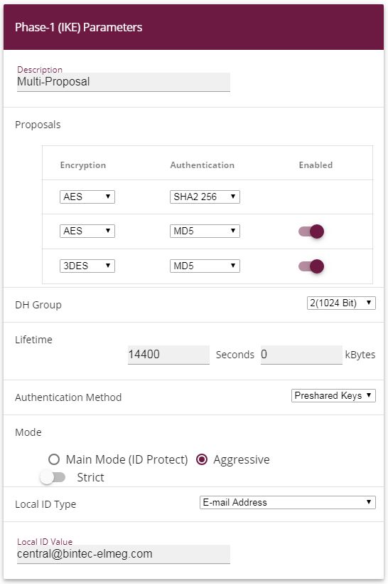
For the Local ID Type, select the type of the local ID, here E-mail Address .
For the Local ID Value, enter a value that can be used to identify the head office gateway, here e. g. central@bintec-elmeg.com .
Leave the remaining settings unchanged and confirm them with OK.
Ping requests are periodically sent to the branch office gateway via both tunnels in order to monitor the VPN IPSec tunnel connections. If this ping request fails to be answered three times, the head office gateway permits no new connections via the tunnel concerned. As soon as the branch office gateway answers the ping request three times once more, new IP connections are permitted. While one VPN tunnel is down, all the data is routed via the remaining VPN tunnel.
When the IPSec peers were being created, unique IP addresses (1.0.0.2 and 2.0.0.2 in this example) were issued for the VPN IPSec tunnel's ping monitoring. These addresses are used to periodically check that the branch office gateway can be accessed.
In the Hosts menu, you can configure an automatic availability check for hosts or interfaces and automatic ping tests.
Go to Local Services->Surveillance->Hosts->New.

Local Services->Surveillance->Hosts->New
Proceed as follows:
The host surveillance can be linked to groups using the group ID. In this scenario, each instance of host surveillance must use a unique group ID.
For Monitored IP Address, enter the IP address of the host that is to be monitored. For the monitoring of the first VPN IPSec tunnel, in our example the monitoring of the branch office gateway is done with the address 1.0.0.2 .
By setting the Source IP Address for host surveillance, you ensure that the ping packet with the local IP address of the VPN tunnel interface has been sent so that the branch office gateway can, in turn, reply via this same route. Select Specific and enter the local IP address of the first VPN IPSec interface, e. g. 1.0.0.1 .
For Interval, enter the time interval (in seconds) which is to be used for checking that the host is available, here e. g. 3 seconds.
For Successful Trials, enter the number of pings that must remain unanswered for the host to be regarded as unavailable. Here, e. g., after 3 failed attempts.
For Unsuccessful Trials, enter the number of pings that must be answered for the host to be regarded as available once more. In our example, a host is regarded as available again after 3 successful ping requests/replies. This function is aimed at preventing frequent jitters in the connections.
Under Actions to be performed, select the Monitor option, because the status of interfaces is not to be changed.
Confirm with OK.
To monitor the second VPN IPSec tunnel, after saving a second entry for host surveillance must be created. Create the second host surveillance entry in the same way as the first entry except for the IP addresses. In the second entry for host surveillance, the local IP addresses of the second VPN IPSec interface are used. In our example, the address 2.0.0.2 is used as the Monitored IP Mddress, and 2.0.0.1 is used for the Source IP Address.
When the configuration is complete, the list of monitored hosts shows two entries that monitor the availability of the branch office gateway's IP addresses.
Results:
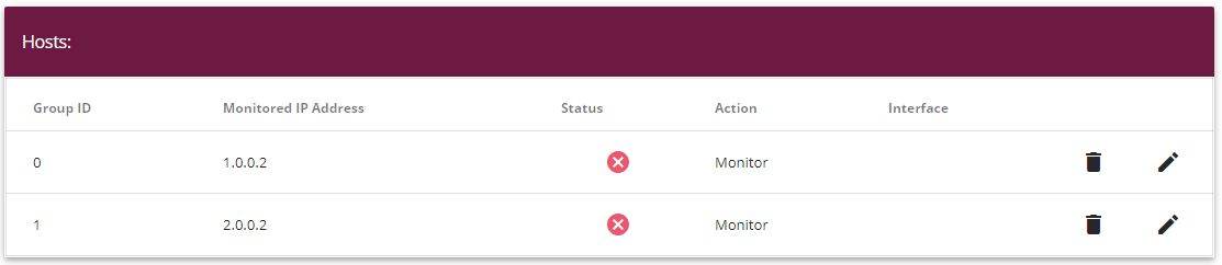
Local Services -> Surveillance -> Hosts
Another load balancing group is created to distribute the IP sessions to the two VPN IPSec connections.
Go to Network -> Load Balancing -> Load Balancing Groups -> New.
Network ->Load Balancing->Load Balancing Groups->New
To create a load balancing group, proceed as follows:
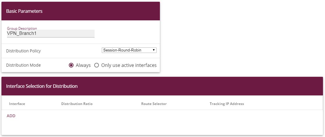
Under Group description, enter a name for the load balancing group, e. g. VPN_Branch1 .
For Distribution policy, select the method that will be used to distribute the data, here Session-Round-Robin (for load distribution based on IP sessions).
The two IPSec interfaces can then be added to this load balancing group.
To do this, click Add.

Network ->Load Balancing->Load Balancing Groups->Add
Proceed as follows:
For Interface, select the first VPN IPSec interface for connecting the branch office, here IPSEC_BRANCH1_PEER-1 .
Enter 50 % for Distribution Ratio. This option specifies the ratio in which new IP sessions are distributed to the interfaces in the IP load balancing group.
In this example, the Route selector is left at None , since no interfaces have been assigned more than once in different load balancing groups.
The Tracing IP Address option is used to select the IP address from the configured host monitoring, e. g. 1.0.0.2 . When the host surveillance detects that the connection has been broken, no more IP sessions are set up via this VPN IPSec tunnel.
Click Apply.
Add the second VPN IPSec interface with Add.
For Interface, select IPSEC_BRANCH1_PEER-2 .
Enter 50 % for Distribution Ratio.
Select the Tracing IP Address, e. g. 2.0.0.2 .
Click Apply.
Results:

Network -> Load Balancing -> Load Balancing Groups
| Copyright© Version 08/2020 bintec elmeg GmbH |